Jeff Duntemann's Contrapositive Diary Rotating Header Image

steampunk

Steampunk Geiger Counter, Conclusion

PillBottleProbe500Wide.jpg

The Geiger counter is still a lashed-up mess of clip leads and greasy junk on my workbench, but as I mentioned in my last daywander, it does work, and detects the radium paint on a couple of sixty-year-old military aviation panel meters. I may not be able to work on it much for the next few weeks, so in this entry I’m going to summarize what I’ve learned so far.

PillBottleProbeDetail350Wide.jpg
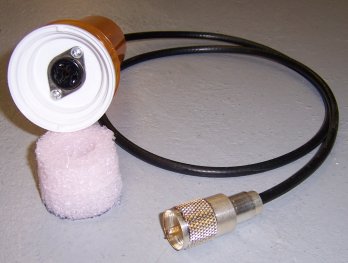
But first, a couple of notes on the probe I made. I noticed years ago that a species of pill bottle with a two-way cap allows two bottles to be connected at the cap. It occurred to me that one of these bottles was by sheer chance just about the size of an Amperex 75NB3 Geiger tube. So I mounted the JEDEC A3-1 socket in the cap, and cut a foam doughnut with an Exacto knife so that it would fit (with just a little compression) inside one of the bottles. A 5/8″ hole in the doughnut keeps the Geiger tube centered and immobile inside the bottle. I put a PL-259 on the cable because I have a lot of PL-259’s here, and they have a pleasing sort of retro look to them, especially after they tarnish. (This one was new from a sealed bag. It won’t look so shiny next year.)

My first conclusion, after a huge amount of time spent trying things, is that it’s not easy getting to 900V with nothing more than a pushbutton, a spark gap, and 3V worth of batteries. In fact, the best I could do was barely break 700V, which is right on the edge of what allows this particular tube to operate. (Smaller tubes like the CK-1026 may work at lower voltages.) Change out the spark gap for a 1N4007 silicon rectifier and you’re at 900V in twenty pushes of the button–more with a larger cap, less with a smaller cap. The transformer matters crucially. The one I’m using has a 1:14 turns ratio, which is very uncommon.

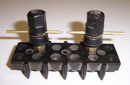
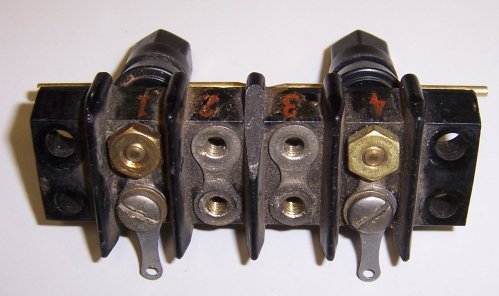
My second conclusion is that the sort of greasy black bakelite barrier terminal strips that I used for the spark gap and general connections are very leaky at high voltage. The caps are mounted on a steatite bar, which is very low-loss, and when I soldered everything else together in a sort of self-supporting wad in mid-air, the charge stayed on the caps almost twice as long. Obvious in hindsight, but I never thought about it when I was putting the thing together. The final device will be assembled with this in mind. If it doesn’t look especially retro, that’s ok.

My third conclusion is that some sort of amplification is necessary. With 900V on the tube I could clearly hear the clicks indicating activity, but they were not loud and this was in a workshop as quiet as most tombs, at least those lacking zombies and poltergeists. I set up a small homebrew two-tube speaker audio amp on the bench (lineup: 6AV6-6AQ5A) and piped the tube’s output into it. Suddenly the clicks filled the room, and I’m guessing that some of those may not have been heard with the tube running barefoot into headphones. A portable hip-hung retro counter would use battery tubes, of which I have many.

I’m still working on several elements of the design, particularly a better way to charge the caps than pushing a button twenty times. I’m almost ready to test a rotary interrupter that will be operated with a crank. I also have a small hand-cranked telephone magneto that generates 120VAC, and much can be done with that.

But as for whether a truly steampunk (i.e., no active devices) Geiger counter is possible, the answer is a qualified yes. A skilled and patient mad scientist from 1900 could do it. He might have to wind his own step-up transformer, but if I can get to 700V with greasy junk and a spark gap, 900V is not out of reach. I consider myself a citizen scientist but I’m not especially mad, and unlike most mad scientists I have a wife, dogs, and a driveway to shovel in colder weather. That being the case, I’m bringing this research project to a close. I will build a Geiger counter, but it’s going to be more 1950 than 1900. I’ll continue to discuss the project here under a different title. Deco Geiger Counter? Deiselpunk Geiger Counter? Still thinking about that, but you’ll know it when you see it.

Steampunk Geiger Counter, Part 5

GeigerCounterLashup1.jpg

Size matters. Last night I swapped a different step-up transformer into my very anemic Geiger counter high voltage generator: a five-pound brick of an aviation power transformer from the early 1960s, with a 465V secondary. I put the interrupted DC into the 5V rectifier filament winding for maximum turns ratio, and then started pumping the buttom.

Way better! Thirty or forty presses got spark every time, and took the voltage across the accumulator capacitor (.5 MFD @ 600V) up to about 620V. That’s not the 700V called out for the Geiger tubes I have, but I think it’ll be plenty to detect the occasional hapless gamma. One problem I knew I would have is that the capacitor leaks charge far too quickly: In about six seconds, the voltage goes down to 300V. Without more stored charge, I’d be pumping the button (or spinning the rotary interrupter, assuming it works) pretty much constantly.

SparkGapCloseup.jpgI ducked over to OEM Parts on my Monday errands wander to peruse their capacitor collection, and picked up a couple of new 1.5 MFD @ 630V caps. Two in parallel provide 3 MFD, which keeps its charge long enough to be useful, assuming the Geiger tube will still conduct with only 400 volts on it. I also turned one of the spark gap electrodes around (see macro shot above) so that the gap is between a point and a flat face. The gap became reliably unidirectional after that, and there were no more sparks on make, but only on break.

Next I tried lashing up the full Geiger counter circuit, with the signal from the tube going into a 2-stage tube speaker amp that I built fifteen years ago. Problems came up immediately:

  1. My 525V DC supply (which I haven’t powered up in almost 20 years) has a bad filter cap, so if there are detector pulses, they’re drowned in the AC buzz. No huge problem, as I can now run the Geiger tube off the pure DC in the larger accumulator cap. (That’s tomorrow night’s project.)
  2. I don’t have a reliable pinout for the Geiger tube. Weirdly, none of the articles in the old magazines show a basing diagram, which is three pins in an odd arrangement on a 5/8″ base. One of the three pins goes to the metal shell, as determined via ohmmeter. I’m assuming that the center electrode is the “lonely” pin, and the third pin goes to the conductive inner surface of the tube. Interestingly, in the junkbox socket I found, the two “close” pins were wired together. I sense some cut-and-try in my immediate future.
  3. I may or may not have a radioactive sample to test it with. I dug my grandfather’s 1953 gold retirement watch out of the curio cabinet, only to find (in defiance of memory) that it did not have a radium dial. My other possible sample is an 0A2WA gas regulator tube, which is salted with .03 microcurie of Krypton-85 to ensure immediate startup. Sounds great–except that the half-life of Kr-85 is 10.7 years. The tube was manufactured in 1962, which is 4.5 half lives ago. Unless I’m doing the math wrong, that means that only 4% or so of the Kr-85 is still in there throwing particles.

Of course, I can pull one of the smoke detectors off the ceiling and try that, but there’s a more intriguing possibility: WWII aircraft equipment meter faces often had radium markings, which are still radioactive even if they no longer glow in the dark. I have three or four old military panel meters from that era, and if I can find them, they may still be active enough to come up out of the background noise.

Assuming that at least one of my two Geiger tubes is good, I’d say we’re getting close.

Steampunk Geiger Counter, Part 4

SparkGapLashup.jpg

Sparks. Let’s talk about sparks. Last night I finally got things lashed up sufficiently to see whether I could translate three volts–a pair of C cells–to the neighborhood of 600 volts, using an old 25,000 ohm : 3.2 ohm output transformer and a spark gap. Got sparks. Didn’t get 600V. (Got about 350 at best) Drained the batteries pretty quickly.

Nonetheless, it was a fascinating experiment, in a technological backwater I’ve never really messed with before. In summary: Put a pulse of current through the low-impedence winding of an output transformer, and a pulse of high voltage (compared to the input voltage) will appear across the transformer’s high-impedence winding. Rectify the pulses, and you can accumulate voltage in a good, high-value low-leakage capacitor.

One way to rectify the pulses is to send them through a spark gap. The air gap breaks down against sufficiently high voltage and current passes one way across the gap. Put a cap in series with the spark gap and it will store a certain amount of charge each time the spark jumps.

At least, that’s how it works in theory. In practice, with a very high resistance voltmeter across the capacitor, I saw two phenomena I wasn’t expecting:

  1. About half the time, I get sparks on both a make pulse and a break pulse. (Ordinarily you only expect a spark on the break pulse.) If both make and break generate a spark, a pulse jumps the gap in the opposite direction as the pulse that preceded it. This means that the charge placed across the capacitor is then of the opposite polarity, which drains the cap by about as much energy as the previous pulse placed in it. Tinkering with the gap spacing didn’t help, though the effect happened more often with a higher voltage (>6VDC) into the transformer.
  2. Eventually, the spark refuses to jump. It looks to me like accumulating a certain voltage on the cap bucks the spark gap and makes it harder to jump with the same pulse from the output transformer. And of course, once the spark ceases to jump, voltage on the capacitor ceases to rise.

With my lashup, once voltage got to about 320, there were no more sparks, with about .003″ across the gap. Putting a stronger current source across the input didn’t help. I was eventually pulsing 12.6VDC from my 30 amp linear bench supply, which heated up the poor transformer pretty badly but didn’t give me any more voltage across the cap. Now, 320V may be enough to get conduction through a Geiger tube (I’ll find out shortly) but the articles I’ve read suggest 600-900V, and seem to think that this can be had from a couple of C cells and a spark gap.

I did better placing a husky 1000 PIV 1N5408 silicon rectifier diode across the spark gap. The charge went up and only up (because current reliably passes only one way through a rectifier diode) but it still topped out at about 350V. I suspect that that limit may be inherent in the relatively small output transformer I’m using, and when time allows I’m going to troll the collection for the largest one I have and swap it in.

Now, a steampunk mad scientist never runs out of #40 copper wire and thinks nothing of winding his own transformers, so if that’s the secret, a steampunk Geiger counter remains a possibility. However, I’m beginning to wonder how well I can achieve the steampunk ideal (no active devices) with only what I have lying around. Winding my own step-up transformer is just on the other side of what I’m willing to do.

The next step is making sure my two Geiger tubes are good by lashing them up to my 525V DC supply and exposing them to a (mildly) radioactive gas rectifier tube. Don’t know yet when I’ll be able to do that (real work has been piling up this week with the two of us trying to recuperate) but I’ll continue the series here as time permits.

Steampunk Geiger Counter, Part 3

With the rash fading and the nerve pain lessening (and Carol safe home!) I stole an hour or so downstairs last night to see what could be done in an hour or so downstairs. And I did well: I got a spark gap together, all made out of junk I’ve had lying around here forever. Not much to it, really: Some brazing rod, two husky black 5-way binding posts, and a battered 4-row barrier terminal strip. I had to drill out two of the holes in the barrier strip to pass a 10-32 thread, but apart from that, the only work was grinding points on two pieces of brazing rod and adjusting the binding posts so that the brazing rod pieces met point-to-point.

SparkGap2.jpg

Done. Didn’t test it; ran out of evening. However, I did put 450V on my capacitor bank to make sure the caps were good, and it took a right-fine charge. It was interesting to watch how quickly the 450V bled off into the probes of a 50,000 ohm/volt VOM. (I miss my old Heathkit VTVM, may have to pick up another.) The more capacitance, the more energy is stored from the spark rectifier, and the longer the counter will run without another crank on the interrupter. So as time allows I’m going to put together a second plug-in cap bank.

The next step is to lash up the interrupter circuit to see if it can charge the caps and make sparks on the above rig. The rotary interrupter still needs some work, but I can clip-lead in an SPST pushbutton switch to give it a go.

Damn, but it feels good to get my hands dirty again. And let me tell you, boys and girls, there is nothing quite like the smell of a gallon milk jug packed full of 40-year-old black Bakelite barrier terminal strips!

Steampunk Geiger Counter, Part 2

CapStack500Wide.jpg

It still hurts like hell to lean back against anything (for latecomers, I’m working through a nasty case of shingles) so I spent a good part of today sitting on my venerable and much taped-up barstool downstairs in my shop, drowning my pain in milk-jugs full of antique electronic parts. As I mentioned yesterday, having tried and failed to do so in 1963, I’m attempting to build a Geiger counter. I’m going to try to do it without active elements; that is, without including an audio amplifier for pulses coming off the Geiger tube. That makes speaker output impossible, but I have 2500-ohm “can” headphones from WWII, which are about as sensitive as that sort of transducer ever gets.

VictoreenGeigerTube500Wide.jpg

The first Geiger tube came with the morning’s mail. It’s a Victoreen OCD-D-103, a NOS spare for the famous yellow Victoreen civil defense portable counters from the 1950s. I actually found a mating 3-pin female connector in my junkbox, which is good, since I have no idea where I’d look otherwise. (The alternative is cannibalizing an octal tube socket for individual pin-grippers, generally by crushing a Bakelite socket in a vice until it crumbles.) Including the pins, the tube is just under 4″ long and 0.625″ in diameter. I’ll have to build a probe housing for it eventually, but near-term I’ll mount it in a pill bottle, of which there are legion.

The top photo is a stack of three 1000-volt mica capacitors, adding up to .048 MFD. That’s about what one circuit calls out, but more is better, and I have a 1950s steatite banana plug bar into which two such stacks will go. So I’ll build a second and put them in parallel. That will get me to about 0.8 MFD, which ought to be enough. If it isn’t, I’ll see what else I can scrounge in the line of high-voltage caps.

I’m modifying an old ceramic wafer switch to be a current interrupter, but I need to get a little farther along before I know if that will work. Those familiar with such switches will understand: I bent down the limit tabs so that the switch shaft can be turned continuously, and at each click current will make-and-break between the wiper and the stationary contacts. Crank it like a Model T, and you generate a series of quick DC pulses to the transformer.

Or that’s the theory, anyway. We’ll see how well it works. More as it happens.

Steampunk Geiger Counter, Part 1

I haven’t really done much in electronics in the last year or two, and I miss it. So when stumbling around in my scanned schematics folder tree, I came across a couple of Geiger counter circuits that I discovered while scanning Carl & Jerry out of Popular Electronics a few years ago. What struck me back then was how little there actually is to a Geiger counter circuit, and, with a Geiger tube in hand, I could have a working counter in a couple of hours or less. (A really ugly clip-lead lashup might take me half an hour.) And although Uncle Louie gave me a Raytheon counter tube when I was 11, I can no longer find it. So up I went to eBay, and discovered to my delight that somebody was selling an Amperex 75NB3 counter tube. This is significant (nay, an omen!) because I’ve been looking for one for a while. It’s the tube called out in a circuit PE published in July 1955, with the cool Ed Valigursky prospector cover. (Scroll down to it.)

GeigerCircuit-PE-July1955-P30-500Wide.jpg

The circuit is simple; nay, minimal: Basically, a 375V DC source applied to the center element of a Geiger tube through a current-limiting resistor. Any time an energetic particle passes through the tube, it ionizes some of the gas inside (generally neon with some trace gases to sharpen the pulse by quenching the trail quickly) and for an instant the tube conducts. You can pick off a pulse through a blocking capacitor and hear it with sensitive headphones as a sharp click.

Getting 375V worth of battery is nontrivial these days, but also unnecessary. Note what happens above: The batteries do nothing but charge a couple of capacitors. A circuit I found in the July 1957 issue finesses high-voltage batteries completely by setting up an output transformer as a step-up, and applying interrupted DC to the output (low impedence) winding. The interrupted DC induces high-voltage pulses in the input (high-impedence) windings, and if you capture them in a capacitor, you can power the Geiger tube from a single D cell.

GeigerCircuitPE07-1957-500Wide.jpg

The one glitch is interesting all by itself: You have to pass the pulse through a spark gap. In this circuit it’s an automotive spark plug (remember those?) but it can be anything you can crank down to a thirty-second of an inch or so. In a similar circuit published in The Boys’ Second Book of Radio and Electronics, Alfred Morgan uses two small nails held in binding posts, and lacking a spark plug in the junkbox, that’s probably what I’ll do. The spark gap acts as a crude rectifier, making sure that only the positive excursion of the induced pulse goes to the hot side of the .05 cap. The interrupted DC is generated by repeatedly pressing and releasing a momentary-contact pushbutton switch. The transistor here is a headphone amp, but again, high-impedence headphones will make pulses audible direct from the tube.

So. Is this really a steampunk technology? In other words, could someone with some skill and knowledge have built one of these in 1900? (Again, the circuit does not require a transistor, nor even a vacuum tube to amplify the pulses.) I don’t see why not. You’d need somebody who understood ionizing radiation, but that’s no stretch for a 1900-era mad scientist in brass goggles. Neon gas in a graphite-coated glass tube? Transformers? Headphones? Kid stuff.

While I’m waiting for the counter tube, I’m going to lash up the cap charging circuit and see how it works. The output transformer called out in the circuit used to be present in every single All American Five clunkerjunker tube radio I found on the curb on Garbage Day, but you may have to ask around for used units, or spend (much) more on a new transformer from Antique Electronic Supply.

And to test it? In my box of gas-regulator tubes I have a couple of old units that were “salted” with something like a trace of Lead-210 to make them conduct instantly when power is applied. Such tubes aren’t very radioactive anymore because the salting materials have short half-lives, and it’s been 55 or 60 years since most were made. And hey, if they really are dead, there’s always a few cosmic rays floating around.

I was told recently that bananas are mildly radioactive. (It’s the Potassium-40.) This seems like a stretch to me, but…we’ll find out.

Daywander

I think a lot of the air is going out of the whole pirates thing; surely I thought there’d be more pirate talk online yesterday, but saw virtually none. Dare we hope that declaring a holiday for a meme may be the kiss of death for that meme? I’m not sure what else will work, as they don’t respond to DDT anymore. So perhaps somebody needs to declare International Walk Like A Zombie Day. I’m open to suggestions on dealing with vampires. Suck Like A Vampire Day? They already do.

The pirates themselves are still out there, even if they’re not talking much. I got a note from the Jolly Pirate last week telling me that he has finally filled a 2 TB hard drive with MP3s, mostly downloaded from Usenet. The collection comes to 350,000 songs. He just grabs whatever gets posted, no matter what it is, and looks for duplicates when he’s bored. (He admits that about 10% may still be dupes; I’m thinking that figure is higher.) This is boggling; I wouldn’t have thought that that many songs had ever been produced in all human history. But what’s more boggling yet is that all 350,000 will fit on a $100 2 TB SATA drive. I asked him how long he’s been gathering them, but have not heard back yet. That’s just under 100 songs per day for ten years. (My guess: he’s been scrounging songs from his friends by the thousands.)

I’m anal about filenames (I’m the Degunking guy, after all) and not a hoarder to begin with, but I’ll bet others have that problem too. Perhaps someone should write a utility that compiles a database of Bayesian signatures for each MP3 file, so to easily spot mostly similar (but not bit-for-bit identical) song files having different titles. Easy Duplicate File Finder doesn’t do this. I’m not an expert at such things, but it might also be able to suggest excessively similar photos (like the endless hundreds we have of various Pack members) that might be deleted and never missed.

I’ve been using the minuscule and frighteningly response Atlantis word processor for odd documents lately, and turned on the sound effects just for jollies. Atlantis plays small sounds at certain times, including a very realistic typewriter click on each keystroke (trust me, I know what those sound like!) a typewriter bell when the line wraps (ditto) and an odd little “mew” like a kitten when it encounters a word not in its dictionary. It also plays a sound like a car horn the first time you touch a key after pressing either Caps Lock or Num Lock, which is surprisingly useful, especially for people like me who watch the keyboard as much as the screen while typing. For awhile I found this annoying, but at some point I ceased to notice it, and now when I type on close-lipped Word 2000 it “sounds funny.” Odd how quickly we adapt to small changes in our environment, quickly making them the norm. Or maybe I just miss my old Underwood Standard.

I had the strange notion today that when I finally get around to building my Geiger counter, I’m going to craft an oak-and-brass case for it, with fluted knobs, shiny trim and whatever other odd touches might be necessary to make it a steampunk artifact. Of course, then I’d need to get with my sister to design the rest of the outfit to match. (“Does this Geiger counter make my butt look small?”)

The shingles rash is spreading around the entire left half of my torso, and is so touchy now that I can’t lean back in my computer chair. So be glad you’re not here; not only am I growing contagious but am also uncharacteristically grouchy. I’ve been making some good progress on the first novella I’ve attempted in almost thirty years, but it’s increasingly difficult to get into flow with the constant electrical-ish prickliness on my back, which morphs into a weird sort of pain with any kind of contact. So I may have to set Drumlin Circus aside for awhile, and continue to gather research on the Pleistocene megafauna. (In the story, all the circus animals are megafauna now extinct on Earth.) I learned yesterday that there was once a 6,000 pound giant wombat, and am trying to get my head around the concept. Whatever else our early human ancestors did, they certainly ate well. For awhile.