
I hung yet more Elfa shelves downstairs the other day, on the only remaining blank wall in my peculiar workshop. I’m trying to get stuff off the floor and into some semblance of order. A number of tube-era radios went up on the shelves almost immediately, including a Heath HW-22A and a pair of Ameco TX-62s, one of which is a parts unit. So did something else: the tube-era thingie shown above, which has been following me around for almost twenty years. I bought it at a hamfest in the early ’90s for a dollar. The old guy who sold it to me didn’t know what it was. I bought it for the sake of the transformers inside, which were worth that much even in 1993. It turns on, lights up, and hums softly. I still don’t know what it’s supposed to do.

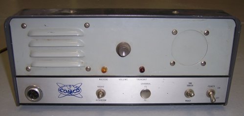
It’s made by Comco Communications Company, of Coral Gables, Florida. Its model number is 642-RCU. From the “RCU” I’d guess a radio control unit, or remote control unit. It has no RF parts inside. There’s an audio power amp with a 6AQ5A driving a speaker behind the grille. The front panel has a 4-pin PTT mic jack, a momentary action toggle switch marked “RADIO” above and “INTERCOM” below, with “RADIO” the default position. A hole marked “CHANNEL” with “T1” above and “T2” below is plugged. A conventional toggle switch is marked “TONE SQUELCH” above and “DISABLE” below, and beside that, an On/Off toggle switch marked “POWER”. At the center of the panel is a rheostat marked “VOLUME,” and two grain-of-wheat lamps, the orange one labeled “RECEIVE” and the red one “TRANSMIT.” A round hole the size of a panel meter is plugged. On the back panel is a fuse holder, a 5-terminal strip for spade connectors marked “PHONE LINES” and and empty rectangular knockout marked “EXT. CONTROL” from which a cut-off 4-conductor cable protrudes. That might have been a hack; the cut-off cable goes directly to the mic connector.
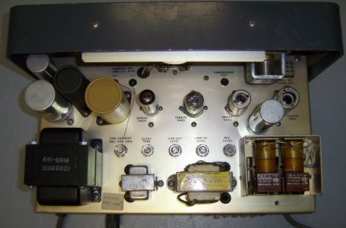
There are two pin jacks on the chassis (see above, just past the tan electrolytic) that say, “CURRENT ADJ. 5MA == 0.5V”. I’m guessing that the meter was dropped from the product to reduce its cost, and the pin jacks provided for service techs. To their right and a little way over is another pin jack labeled “COMPRESSOR TEST.” No idea on that one.
The tube complement is: 12AX7, 6BA6, 12AU7, 6AQ5A.
I suppose it might be some kind of phone patch, though it doesn’t look like any phone patch I’ve ever seen. The “RADIO / INTERCOM” switch throws me a little, since there’s no external connector for intercom lines. I haven’t traced the tangles under the chassis to any extent yet, so if I don’t know precisely what it does, it’s partly my own fault.
And I have other things to do. Even my voracious curiosity has its limits. If you’ve ever seen one of these or want to hazard a guess, please do!


FWIW, I’m thinking some sort of Muzak box with a rudimentary PA system built in. The “radio” signal (music) comes in over the phone line, but you can interrupt it to announce those blue-light specials. Imagine it as an add-on to a basic Muzak phone-to-speakers-everywhere system. Any chance the 5 phone connections are 2 in, 2 out, ground? That would let it set between the phone lines and the real Muzak box.
I had to go down and open it up again, but yes, the five terminals on the back apron are 4 phone leads, plus a fifth for ground. I hadn’t thought of muzak! That might explain the test point on the chassis marked COMPRESSION.
This could be a control for a pneumatic tube system, possibly used in a bank. I was a Field Service Technician in the late 70’s, and “TRANSMIT ” was a term used for sending of the carrier, and compressors moved them back and forth.
I note that there is still a ComCo which makes pneumatic tube delivery systems. They claim to have been in business since 1968. Of course, their current logo looks nothing like the one above, and the current corporate headquarters is in Dallas, Texas, not Coral Gables, Florida.
A little research turned up some history, but nothing about this particular unit. Apparently, Communications Company, Inc. was a provider of specialty radio gear starting in the 1940s – police/fire, ship-to-shore and marine, military, taxicabs, etc. They became known as ComCo, and they were fighting it out with Motorola and others for domination of those specialty markets. They were apparently slow to make the move to solid state, which left them at a significant disadvantage to Motorola. Sometime in the late 1960s or early 1970s, E F Johnson bought them, and the ComCo name slowly disappeared.
Based on what I’ve found, I’d guess you have the head (control) end of a two-piece unit. Does the chassis frame give any clues as to how (or where) it might be mounted?
It’s not an under-dash unit, or else the brackets were very cleverly hidden. Agreed; I intuit that it’s a control head of some sort, or perhaps an integrating device that knits together telephone and radio signals into something that a desk-based listener could send out onto a PA/intercom system.
Comco made some very nice UHF FM repeater systems. Tampa Airport had one when it opened in 1970 that was used for communications by the maintenance crews.
You most likely have a 2 wire remote for one of their FM systems. You can send and receive audio over a DC phone line to the remote radio. By sending different currents along and using polarity shifts you switch frequencies, unsquelch receivers, key the transmitter, etc. You can have two or more of these hooked up in parallel, so the intercom function was to talk to the other unit without keying the radio it controlled. It was all done without software and computers …
My friend Joe Flamini suggested precisely that: A phone-based remote repeater controller. I think we’re closing in on it…
It’s a remote control unit for a two-way transmitter. Comco made FM gear for the normal low, high and 450 MHz bands but also made some 110-130 MHz AM gear for the aviation market. In many cases, the RF gear was located on a nearby mountaintop or remote tower, some distance from the dispatch point.
The control unit connects to the transmitter/receiver via leased telephone lines and superimposed a DC current through the line to control the T/R function at the remote end. By sending current instead of voltage, the resistance of the phone line became immaterial, within reason. (There’s a maximum permitted voltage and current allowed by the telephone company, of course.) And the telephone company was well known for changing the particular routing of leased lines as it added or changed its outside plant facilities.
Some remote control units had multiple current settings to do things such as selecting frequency 1 or 2. This would be done by relays with different current ratings or shunting resistors.
Audio is applied and taken off with a transformer with two windings on the wireline side and a series capacitor between the windings. This allows the DC to be duplexed over the control pair along with the audio. At the remote station end the same arrangement is made, except the blocking capacitor is bridged with the T/R relay coil.
[…] Flamini and Jack Smith are both pretty sure that the mysterious Comco gizmo I presented in my February 6, 2012 entry is an early remote control unit for commercial and public service radio systems, allowing […]
I also have a Comco mobile unit , model 404DCFG. Looking for any info on this model.
Thanks
Dave
What is that model, functionally? Controller? Radio? Repeater? A whole lot of old radio manuals were posted on alt.binaries.e-book.technical a year or two ago. They may have scrolled off by now but I’ll take a look. If you collect old gear like that it’s actually a good thing to monitor once in a while.
Jeff: Thanks for your prompt and courteous reply, I believe the radio was used to communicate between aircraft and the ground crew, mabye an AM radio for fuel and other things , I know that it takes up bandwith to post pictures, I haven’t seen any like it after looking at hundreds of radio pictures, I have searched for manuals , or info for some time and found nothing on this model. I like hand made things , don’t see much of that any more.
Some more info on the unit: It has a automotive type antenna connection instead of a UHF connector, it has 18 small tubes , a delco vibrator ( 6 volt ) , what may be 8 adjustable inductors can type.
I also found out that Comco was a subsidary of E.F.Johnson but have found nothing on the Johnson database on this model.
If you want some pics , e-mail me as this will save bandwith, here.
many Thanks
Dave
I looked at alt.binaries.e-book.technical, but nothing from Comco was there. Web trawling may be your only option. You can get search notifications from Google, which work very well on something like a model number where you don’t get a lost of false hits. You might put a saved search on eBay, not only on the model number but also for the string “Comco” itself.
Good luck with it–the vintage gear hobby is full of surprises!
Jeff: Thanks, have pics of the radio on radioreference and a discription on qrz. Will keep searching, mabye someone will have some info on it.
Thanks
Dave
I have a similar story but with a COMCO 680. I believe this unit to be an old police radio, but I’m just guessing.
I was an engineer working for Comco from 1961 to 1966. Unit pictured is a remote control unit designed to control a remote radio over to a metallic telephone line. The transmitter was activated by superimposing direct-current on the line. The current would activate a relay located with the radio transceiver. A VU meter was an optional extra. The intercom switch would allow talking on the telephone line without activating the current. This would allow operators to talk to each other when multiple control units were attached to the line at different locations.
Many thanks! That nails it, though some of my other readers came close pretty close. I sold the Comco unit with a biggish lot of other vintage gear last month, as we’re moving to a smaller home and I really had no place to keep it. Some of it, like my Hammarlund HQ-145X, I will miss. The Comco was interesting, and although I’d have liked to put it in the hands of someone who could actually use it, I suspect that chances of that are low to nil.
Again, thanks for commenting and clearing it all up!
Hello All, I’m not a member here, I just happened by, and read about the Comco “thingie” I’d like to add to this thread, that I also have a Comco
thingie, except mine isn’t a thingie, it’s a military low band VHF transceiver.
It’s a NAVY DEPT. B.O.S. RADIO SET, AN/VRC-33A, SERIAL A16. It has a
wide voltage range of 6.6/13.2/26.4VDC. It’s an FM 2 freq. (but only 1 currently being used) at 40.000Mhz. Dual conversion receiver, with a
6146 final, which is rather large, for a radio that’s only using a single vibrator supply !! One might consider either a 2E24/2E26, but 6146 ??
There’s 1 SO-239 RF connector, with 2 Cinch-Jones ?? connectors, for power and control head. It’s housed in a military gray metal cabinet, with 4, whatever you call-em hold-down clamps. I guess what I’m looking for, is the schematics for this “thingie” I’ve been wanting to get operational for the longest time !! I’ve tried just about everyone, even
BAMA, and they don’t have them !?!? What I’m trying to say is, HELP !!
If anyone out there knows of, or has the schematics for this, PLEASE,PLEASE, let me know !! Should anyone want for photos of it,
just send me your email address, and I’ll send them too you. Thank’s
ahead of time, for any help anyone sends me !!!! Chuck
P.S. simply reply here, I’ll be watching for someone’s reply !!
You don’t have to be a member to post. Everybody’s first post is moderated; it’s just the way the system is set up, mostly to discourage drive-by haters. I’m very glad you stopped in.
I’ve never heard of a Comco VHF rig, and that certainly wasn’t what I had, which contained no RF section of any kind. I sold my Comco unit with a number of other largish radios and electronic gimcrackery because my wife and I are moving to a smaller house now that I’ve retired. I hope someone here has heard of this and will post links and/or photos. Good luck and thanks again for the post!
Was at COMCO 17yrs, most guessed right, standard base station remote
control for over phone line.
Hate to resurrect an old thread, but going to do it anyway.
At a local airport here, there is a Comco 779 aeronautical ground station transceiver. Its been handed down over the decades and the manual is long gone. It still works, mostly. I’ve been searching for any information on this model, but have yet to find anything acknowledging that it ever existed.
The receiver works. The mic cable is loose (and is in need of some level of repair) so the transmitter doesn’t always key up when the button is pushed. Several lights on the front are out and need to be replaced (unknown type). It appears there was at one time a colored protective cover over a couple of them, but I believe those covers broke off long ago.
The big question- there’s a switch on the transmit panel that has “AOC, R-1M, T-1M, T-2M, PA, A-12, A-24”. Does anyone have an idea what these mean?
I don’t know myself, but it might help to post a photo or a link to a photo. I don’t think that was the model I had. Others here are more familiar with them.
Here’s a photo of the 779:
https://www.flickr.com/photos/migrashgrutot/48110503942/